https://www.geeksforgeeks.org/max-flow-problem-introduction/
1. Naive Greedy Algorithm Approach (May not produce optimal or correct result)
Greedy approach to the maximum flow problem is to start with the all-zero flow and greedily produce flows with ever-higher value. The natural way to proceed from one to the next is to send more flow on some path from s to t
How Greedy approach work to find the maximum flow :

There is a path from source (s) to sink(t) [ s -> 1 -> 2 -> t] with maximum flow 3 unit ( path show in blue color )


After removing all useless edge from graph it’s look like

For above graph there is no path from source to sink so maximum flow : 3 unit But maximum flow is 5 unit. to over come form this issue we use residual Graph.
https://www.geeksforgeeks.org/ford-fulkerson-algorithm-for-maximum-flow-problem/
Greedy approach to the maximum flow problem is to start with the all-zero flow and greedily produce flows with ever-higher value. The natural way to proceed from one to the next is to send more flow on some path from s to t
How Greedy approach work to find the maximum flow :
E number of edge
f(e) flow of edge
C(e) capacity of edge

1) Initialize : max_flow = 0
                f(e) = 0 for every edge 'e' in E

2) Repeat search for an s-t path P while it exists.
   a) Find if there is a path from s to t using BFS
      or DFS. A path exists if f(e) < C(e) for
      every edge e on the path.
   b) If no path found, return max_flow.
   c) Else find minimum edge value for path P

      // Our flow is limited by least remaining
      // capacity edge on path P.
      (i) flow = min(C(e)- f(e)) for path P ]
             max_flow += flow
      (ii) For all edge e of path increment flow
             f(e) += flow

3) Return max_flow
Note that the path search just needs to determine whether or not there is an s-t path in the subgraph of edges e with f(e) < C(e). This is easily done in linear time using BFS or DFS.
There is a path from source (s) to sink(t) [ s -> 1 -> 2 -> t] with maximum flow 3 unit ( path show in blue color )
After removing all useless edge from graph it’s look like
For above graph there is no path from source to sink so maximum flow : 3 unit But maximum flow is 5 unit. to over come form this issue we use residual Graph.
2. Residual Graphs
The idea is to extend the naive greedy algorithm by allowing “undo” operations. For example, from the point where this algorithm gets stuck in above image, we’d like to route two more units of flow along the edge (s, 2), then backward along the edge (1, 2), undoing 2 of the 3 units we routed the previous iteration, and finally along the edge (1,t)

backward edge : ( f(e) ) and forward edge : ( C(e) – f(e) )
backward edge : ( f(e) ) and forward edge : ( C(e) – f(e) )
We need a way of formally specifying the allowable “undo” operations. This motivates the following simple but important defnition, of a residual network. The idea is that, given a graph G and a flow f in it, we form a new flow network Gf that has the same vertex set of G and that has two edges for each edge of G. An edge e = (1,2) of G that carries ?ow f(e) and has capacity C(e) (for above image ) spawns a “forward edge” of Gf with capacity C(e)-f(e) (the room remaining) and a “backward edge” (2,1) of Gf with capacity f(e) (the amount of previously routed ?ow that can be undone). source(s)- sink(t) paths with f(e) < C(e) for all edges, as searched for by the naive greedy algorithm, correspond to the special case of s-t paths of Gf that comprise only forward edges.
The idea of residual graph is used The Ford-Fulkerson and Dinic’s algorithms
Given a graph which represents a flow network where every edge has a capacity. Also given two vertices source ‘s’ and sink ‘t’ in the graph, find the maximum possible flow from s to t with following constraints:
a) Flow on an edge doesn’t exceed the given capacity of the edge.
b) Incoming flow is equal to outgoing flow for every vertex except s and t.
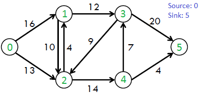
For example, consider the following graph from CLRS book.

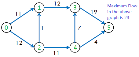
The maximum possible flow in the above graph is 23.


The maximum possible flow in the above graph is 23.

The following is simple idea of Ford-Fulkerson algorithm:
1) Start with initial flow as 0.
2) While there is a augmenting path from source to sink.
           Add this path-flow to flow.
3) Return flow.
Time Complexity: Time complexity of the above algorithm is O(max_flow * E). We run a loop while there is an augmenting path. In worst case, we may add 1 unit flow in every iteration. Therefore the time complexity becomes O(max_flow * E).
How to implement the above simple algorithm?
Let us first define the concept of Residual Graph which is needed for understanding the implementation.
Residual Graph of a flow network is a graph which indicates additional possible flow. If there is a path from source to sink in residual graph, then it is possible to add flow. Every edge of a residual graph has a value called residual capacity which is equal to original capacity of the edge minus current flow. Residual capacity is basically the current capacity of the edge.
Let us now talk about implementation details. Residual capacity is 0 if there is no edge between two vertices of residual graph. We can initialize the residual graph as original graph as there is no initial flow and initially residual capacity is equal to original capacity. To find an augmenting path, we can either do a BFS or DFS of the residual graph. We have used BFS in below implementation. Using BFS, we can find out if there is a path from source to sink. BFS also builds parent[] array. Using the parent[] array, we traverse through the found path and find possible flow through this path by finding minimum residual capacity along the path. We later add the found path flow to overall flow.
The important thing is, we need to update residual capacities in the residual graph. We subtract path flow from all edges along the path and we add path flow along the reverse edges We need to add path flow along reverse edges because may later need to send flow in reverse direction (See following link for example).